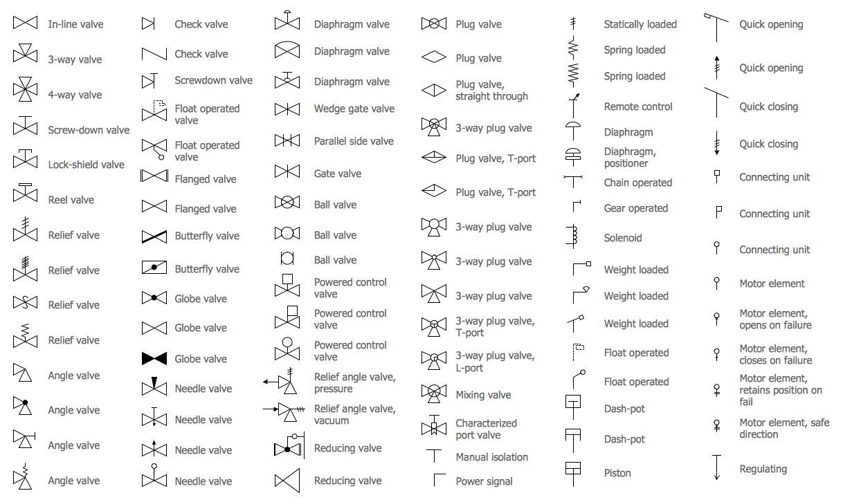
All the best Mechanical Engineering Drawing Symbols Pdf Free Download 36+ collected on this page. Feel free to explore, study and enjoy paintings with PaintingValley.com. All these engineering drawings are available for free download in 2D and 3D pdf formats. ASME Y14.5 and Y14.5M 2009 is the widely used engineering drawing standards for Geometric Dimensions and Tolerances (GD&T). Mechanical Engineering solution — 8 libraries are available with 602 commonly used mechanical drawing symbols in Mechanical Engineering Solution, including libraries called Bearings with 59 elements of roller and ball bearings, shafts, gears, hooks, springs, spindles and keys; Dimensioning and Tolerancing with 45 elements; Fluid Power Equipment containing 113 elements of motors, pumps, air. Mar 14, 2020 - Mechanical Engineering Drawing Symbols Pdf Free Download at mechanical engineering drawing symbols.
If you haven’t found a reliable place to get PDF files of Mechanical Engineering Drawing Symbols PDF free download , I will be giving a reliable place where you can download Mechanical Engineering Drawing Symbols PDF free download in PDF format and save yourself the stress that comes with looking here and there for it in ignorance.
Guess what? You never have to search endlessly for your PDF books when Stuvera is here just for you. At Stuvera just at your fingertips you can download Mechanical Engineering Drawing Symbols PDF free download or read it online for free with no registration involved. So take advantage of the chance to get a free copy of this book online for free, you shouldn’t have any issue accessing this book together with other PDF books on this PDF BOOK SITE.
Engineering Drawing Abbreviations And Symbols - Technical ...


ABOUT THE BOOK Mechanical Engineering Drawing Symbols PDF free download

Mechanical Engineering Drawing Symbols Chart
The Manual of Engineering Drawing has long been recognised as the student and practising engineer’s guide to producing engineering drawings that comply with ISO and British Standards. The information in this book is equally applicable to any CAD application or manual drawing. The second edition is fully in line with the requirements of the new British Standard BS8888: 2002, and will help engineers, lecturers and students with the transition to the new standards.
BS8888 is fully based on the relevant ISO standards, so this book is also ideal for an international readership. The comprehensive scope of this book encompasses topics including orthographic, isometric and oblique projections, electric and hydraulic diagrams, welding and adhesive symbols, and guidance on tolerancing.
Written by a member of the ISO committee and a former college lecturer, the Manual of Engineering Drawing combines up-to-the-minute technical accuracy with clear, readable explanations and numerous diagrams. This approach makes this an ideal student text for vocational courses in engineering drawing and undergraduates studying engineering design / product design.
Colin Simmons is a member of the BSI and ISO Draughting Committees and an Engineering Standards Consultant. He was formerly Standards Engineer at Lucas CAV.
* Fully in line with the latest ISO Standards
* A textbook and reference guide for students and engineers involved in design engineering and product design
* Written by a former lecturer and a current member of the relevant standards committees
Mechanical Engineering Drawing Symbols And Their Meanings Pdf
Paperback, 308 pagesPublished January 8th 2004 by Newnes (first published June 2nd 1994)Original TitleManual of Engineering Drawing: To British and International StandardsISBN0750651202 (ISBN13: 9780750651202)Edition LanguageEnglish